What is Semi-conductor PCB?
In defining a semiconductor PCB, we have first to understand what a semiconductor is.
A semiconductor is a substance which exhibits the characteristics of both a conductor and an insulator. Under certain conditions, it can conduct electricity.

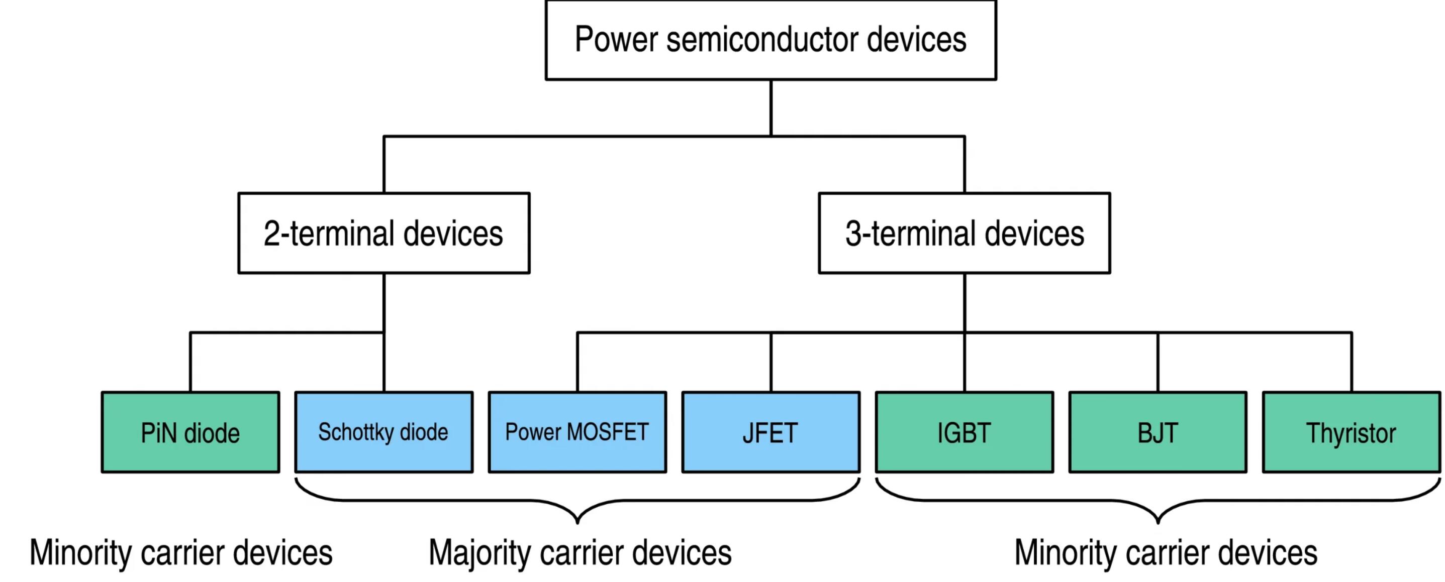
Semi-conductor classification
This quality makes it the most preferred medium when there is need to use electrical power in a controlled manner.
A semiconductor PCBs, therefore, can be defined as the base component on which a semiconductor device is connected.
Benefits of Semi-conductor PCB
Some of the main benefits of semi-conductor PCBs include the following:
Ability to direct flow of electric signals. This ensures that they are well regulated resulting into proper working of electrical devices.
Semiconductor PCBs are small in size. This has led to smaller and faster semiconductors.
Semiconductor PCBs are also less noisy compared to vacuum tubes.
The small size of semiconductor PCBs enables compatibility, which is very necessary for efficiency in electrical devices that use them.
Semiconductor PCBs are also way cheaper compared to the vacuum tubes.
Devices made using semiconductor PCBs are also shockproof and have a longer lifespan.
Semi-conductor PCB Designs & Fabrication
Now, this is a critical stage when you want to make printed circuit boards. Any mistake at this point will affect the performance of your electrical and electronics system.
Semiconductor PCB Fabrication
This refers to the process through which a semiconductor PCB is created. The steps involved can be narrowed down to four major classifications.
Semiconductor Development Requires High Quality for PCB and PCBA
Each step in bringing semiconductors to market involves robust testing. Properly evaluating the performance of integrated chips requires removing as many other variables as possible. Engineers simply can’t afford to spend time debugging boards when evaluating their ICs.
Hitechpcba’s platform collects and analyzes hundreds of datapoints at each step in our automated PCB assembly process, ensuring each board that comes off the line is made to your exacting standards. Our digital thread throughout our smart factory delivers best-in-class results for even the most complex boards.

PCBAs for Semiconductor Development
Validation Boards
No matter how complex the board, Hitechpcba delivers first-time-right Validation Boards quickly. Engineers are then able to test their ICs with confidence, iterate their board designs if necessary, and move into the next stage of semiconductor development.
Characterization Boards
Hitechpcba’s automated production lines can quickly manufacture more complex boards up to the demands of the most rigorous voltage, temperature, and frequency ranges. Engineers trust Hitechpcba to produce the boards that won’t fail, allowing for more confident testing of their ICs.
Evaluation Boards
Hitechpcba offers on-demand production of evaluation boards in quantities from 1 to 1,000+. With Hitechpcba, you can let your customers focus on testing you chips, not debugging boards.
Development Boards
By pushing the limits of what is manufacturable, Hitechpcba's Smart Factory can meet the needs of the most demanding and complex development boards.

The Guide to PCBA Development for Semiconductor Applications
In developing and showcasing new ICs (integrated circuits), semiconductor engineering teams rely on high-quality PCBAs (printed circuit board assembly) for both meeting internal product development timelines and as external sales and marketing tools for customer use.
To help accelerate and streamline silicon release-to-market, Hitechpcba Automation has developed The Guide to PCBA Development for Semiconductor Applications, which contains best practices for post-silicon PCBA design and development, underscores the benefits of early engagement with manufacturers during DFMA (design for manufacture and assembly) — and most importantly, helps engineering teams better meet critical path milestones and improve board quality.
Download this useful guide to learn about:
Post-silicon PCBA best practices
Environmental constraints, design standards, and quality requirements
Design for operation, manufacturing, and test
Accelerating development through manufacturing partnerships
Through Hole Assembly on Semi-conductor PCB Assembly
When this technique is used, through-hole components get to be mounted on the printed circuit board. The semiconductor components have leads which get them through the drilled holes.
After insertion of the components through the holes, the leads are soldered on the opposite side of the board. The soldering process is either automated or manual.
Step 1.Preparation of the surface that is supposed to be soldered is prepared. This enables the surface to be easily attached to the solder.
Step 2.This step involves the placing of the components on the board. These semiconductor components are inserted into the holes to enable soldering.
Step 3.The moment you have inserted the leads, you are supposed to heat them and the pads. This will enable the solder to melt.
Step 4.The next step is the application of the solder to the joint.
Step 5.The meeting point of the solder and the joint are supposed to be touched. This is done with an iron until when the adequate solder is flown. You are then supposed to leave the solder board to cool.
Inspection to ascertain whether the board has been made properly is done. This process has the advantages of easy prototyping and high heat tolerance.
They have better heat handling capacities and leads to stronger physical connections.
Semiconductor boards differ from most other custom PCBAs because they are not intended for a single application. Instead, these boards are meant to be applied widely and across many different industries. The boards may be used as samples to display capabilities, or they may be installed into a larger system for faster bringup. When designing and building semiconductor boards, reliability is the key attribute, regardless of how the board is utilized.

Surface Mount Technology on Semi-Conductor PCB Assembly
This involves mounting of semiconductor components on the printed circuit board. It is widely preferred today compared tom through-hole assembly.
Components here are not inserted through holes. Leads are located under the packages. This makes contact with the surface of the board.
This is a complicated process that can never be undertaken manually.
Its main advantages are that they are automated and as such, they are simpler and faster. It also enables the making of smaller but very powerful designs which are also lighter.
This is owed to the fact that both sides are available for mounting semiconductor components.
It is also preferred because of its higher load capacity compared to through-hole assembly.
Semiconductor components mounted by SMT are likely to have lower resistance and inductance. This technique also has the advantage of higher production capacity compared to the through hole technique.
Optimized PCBA Manufacturing for Semiconductor Development
At Hitechpcba, we build boards that are IPC Class 3 compliant and meet IPC-6012DS Class 3A standards for medical applications. We source components from a wide network of reliable suppliers offering authentic components with full traceability. We offer consigned inventory options, with inventory controls built into our quoting, DFM, and manufacturing processes.
Our smart factory in China uses advanced software at every stage of assembly. This digital thread manufacturing process allows us to build high-quality boards quickly, and at quantities from 1-1,000+.
During the build process, boards pass through multiple checkpoints and inspections to ensure quality, including AOI and X-ray inspection. ROSE tests validate the cleanliness of in-line washing. All reworks are traceable back to the board, component location, and process.

 Chinese
 English
 Russian
 Spanish
 Portuguese


