What is a PCB Gerber File?
What is a PCB Gerber File?
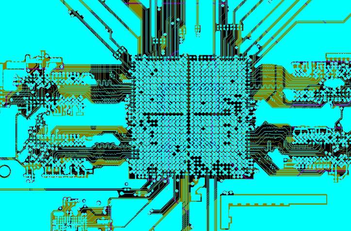
A Gerber File is a software file that is provided to the PCB Manufacturing Company to fabricate a PCB to the required specification. A PCB Gerber file is a two-dimensional pictorial representation of each layer of a PCB board where tracks, pads, and vias are represented by different lines and shapes. It is the universal way of telling a machine how to create a PCB board based on the information provided. The Gerber file is the very first step of fabricating a PCB board. It is a widely accepted PCB designing standard among manufacturers and customers.
The PCB Gerber File stores all the information such as track width and length, Hole spacing, copper amount, etc. This data is very crucial to design a PCB board so that the end application can be served. It simply looks like an image of the PCB layer and its elements.

Gerber File Format
The Gerber File format is named after the Gerber Scientific Instruments Company, a pioneer in photoplotter manufacturing. The original Gerber format was the EIA RS-274D standard, which consisted of a command file for each conductive layer and a tool description file. The command file consisted of a series of short commands, each followed by a set of X and Y coordinates. These X-Y coordinates were used by a photoplotter to create a graphic.
The Gerber file is software-independent so it can be used by all PCB fabrication companies no matter what equipment or software they use. The most commonly used Gerber file format is ‘RS-274X’ It includes commands and coordinates for drawing lines and shapes. This format is available in human-readable test. It gives the ease to open the file in the text editor to see the commands.
Versions of Gerber Files: There are three versions of Gerber formats.
• Gerber X2: The latest Gerber format with stack up data and attributes.
• RS-274-X: An expanded version of Gerber format and is it used widely.
• RS-274-D: The oldest version of Gerber format which is slowly replaced by RS-274-X.
Each Gerber file represents only one PCB layer. For instance, if you have a two-layer board then a total of seven Gerber files will be required.
Board Outline
Copper Layer (Top)
Copper Layer (Bottom)
Solder Mask (Top)
Solder Mask (Bottom)
Silkscreen Layer (Top)
Silkscreen Layer (Bottom)
Drill
Gerber Data: It is an ASCII text file, which contains four elements: Configuration Parameters, Aperture Definitions, XY coordinate locations for commands, and Command Codes. After opening the Gerber file in the text editor, you can easily read the ASCII data. It gives you the leverage to modify the data if any design problem occurs. Nowadays, the Gerber files also include information for the layer function, pad types, locations of impedance-controlled traces, etc.

0086-755-29970700
sales@hitechpcb.com; sales@hitechcircuits.com
3F, B5 Dong, Zhimeihuizhi, FuYong, Bao’an Dist. Shenzhen, GuangDong, China 518103
 Chinese
 English
 Russian
 Spanish
 Portuguese


